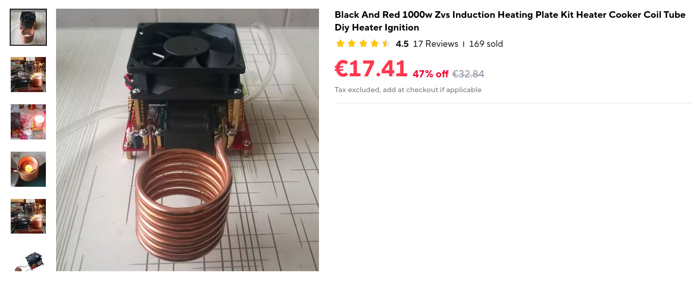
Sometime back in the Winter of 2025 I have ordered a 25€ 1kW induction heating board off Aliexpress and put myself up to the task of closing my teenage gestalt of High Temperature Chemistry.
The state of documentation around the thing was quite pitiful and I made a large amount of costly mistakes while trying to get it to run. Herein is a more detailed look at the board and a compilation of some of the more notable failures and setbacks I have encountered over the last year of sporadically working on it whenever my situation has allowed me to. This is hopefully part one of a longer series of improving this induction heater and using it to carry out high temperature chemistry without resorting to using obscene amounts of gas or buying a bulky, expensive and prone to failure resistive furnace.
Part 0, Gathering Hardware and Initial Setup
In the really scuffed cardboard box (not the one pictured) there really wasn’t much included except the board itself, a cooling fan, some silicone tubing for watercooling, a copper work coil and some standoffs and washers for attaching the cooling fan and for the connection of the work coil to the actual board (more on that later).
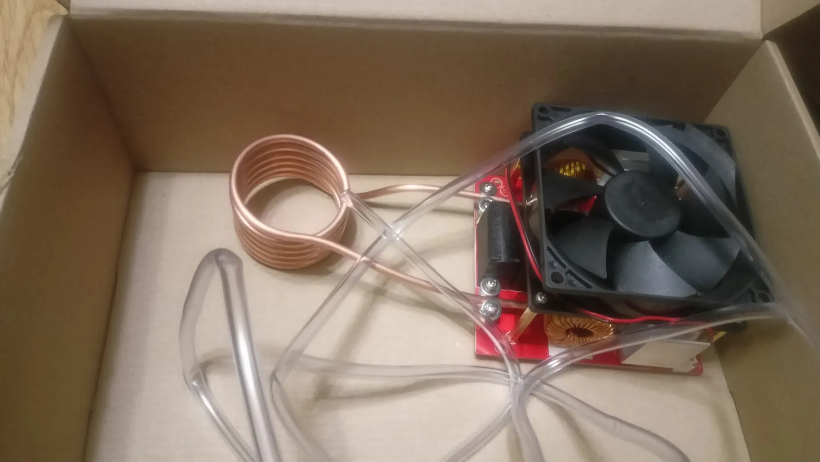
(it didn’t come preassembled, i just really couldn’t bother with taking it apart and the assembly is mostly trivial anyways.)
The work coil is made out of 6 windings of copper tubing (ID/OD: 2mm/4mm) with the coil itself having the innner and outer diameter of 45mm and 53 mm respectively. Which is quite small for an induction furnace (most crucibles you can buy are bigger than this), and my uneducated guess would be that this is more aimed at annealing metal parts or heating seized steel nuts or bolts.
The board itself is based on a quite simple ZVS topology1 and the most complex bit of silicon on it (aside from the fading RGB LED) is an op-amp used as a current comparator/soft starter (?) for the basic on-board overcurrent protection functionality. Which is nothing more than the comparator and a simple two-transistor latch, with a button to disengage it. The topology being as simple as this is quite convenient as unlike with the more complicated “proper” topologies it is self-tuning, and requires no adjustment from the end user. The downsides are decreased efficiency and the inability to tune the frequency or to easily turn the circuit on or off without a powerful switch.
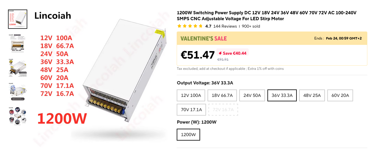
Now, one of the big catches is that powering this thing is really non-trivial unless your lab is already geared for power electronics. As it does draw well above 20A at 36V, getting away with a laptop wallwart is really not an option this time.
An optimal solution for this is either a high power (36V, 1kW+) general purpose switching power supply (can be had on aliexpress for relatively cheap), or a used/surplus server power supply. My initial idea for powering it was to simply use a 1.8kW variac and a really big bridge rectifier, but this turned out to be horribly unsafe and very impractical and expensive for what it was. I went with option A and shelled out the 40 or so euros for a 1.2 kW switcher.
The connection between power supply and board was made with thick copper wire and XT60 connectors, which can handle these kinds of current quite well and are a much cheaper and convenient option than any other connector of this category (though I am open to suggestions if you have any). Screw terminals are the reason I have carpal tunnel syndrome and anger issues.
Oh, and water cooling ended up mostly superfluous for short test runs or small scale metal melting, and will not be looked at in detail here, as for the time being the water cooling system is really nothing more than a pile of tubes and and a pump laying unused in a cardboard box.
Part 1, Misery and Failure
The first run, mostly due to operator mistake, proved to be a huge disaster. While there is built-in OC protection, it is mostly powerless against blatant abuse. In an attempt to get a stainless steel screwdriver red hot, the “unlatch” button was rapidly mashed in what can only be described as a moment of childish impatience and utter desperation. Obviously, such machinations combined with the 20 or so amps flowing through the circuitry will lead to destructive consequences. The casualty toll on that fateful day ended up being 3 power FETs, a trace on the board and a BJT used for the current protection latch.
The fan ceased to spin, and the overcurrent indicator LED was now stuck, taunting me with its rainbow shimmer. This set me back 10$ worth of parts and a whole evening worth of my time. The suspicious failed FETs were replaced by brand new IRFP250Ns, and the high current N-channel MOSFET was swapped out for a similar enough IRF3205P2.
Now that the board was rejuvenated and probably better than ever, a succesful heat test was carried out, with the same screwdriver no longer causing the protection to trip, and the test pieces of various susceptible metals now easily getting up to red hot within the work coil. Now onto the crucibles.
Part 2, Crucible Woes
Now, for most purposes, graphite crucibles work largely fine in induction furnaces. They are cheap, very susceptible to eddy currents, and are easily available on the internet. For my applications however, there was a slight problem. That being the relatively high reactivity of red hot graphite. The well behaved graphite is quite a strong reducer when heated to incandescence, and a major source of anxiety for me. Now, in metallurgy, this is actually beneficial, in that field, red hot carbon is a commonplace reducing agent, used in many industrial reduction pathways to metals and chemicals3. This is highly concerning for someone who has a deep carnal urge to sinter and melt various reactive oxides.
My first idea of a solution to this was to switch vessels to ones made of another material, namely to Silicon Carbide. Silicon Carbide is another viable material for such matters, and is commonly encountered in crucibles intended for microwave melting of glass and metals, which nowadays can be had online for relatively cheap. But there are some issues with this approach. SiC is usually mixed in with graphite in such crucibles, and not all such crucibles are born equal. The cheap, crude-looking vessel that I had ordered from Aliexpress was doing a terrible job as a susceptor. Barely heating up to 250 degrees C, it could boil water and fell just short of roasting ammonium metavanadate, requiring the placement of a screwdriver inside of the crucible for providing the extra heat. Though that did deposit a beautiful thin film of vanadium oxides on the screwdriver, this was not a viable option.
The attempts at using a conventional graphite crucible were also not without hangups, as the crucibles I got (40*40mm) were too big, and ended up being too strongly coupled4 to the work coil, causing the overcurrent protection to instantly trip, with nearly no heating happening in the process. In my final attempt to use this work coil, the standard-sized graphite vessel was replaced by a tiny one with the OD of 22mm, which thankfully easily got up to red hot within 30 seconds.
After rereading the listing page for this device, I have found out that they do actually recommend using a 30*30mm graphite crucible. My bad. Though in my defense, it is nearly impossible to find such a crucible either locally or on Aliexpress.
Part 3, Almost as Good as Tolerable
The first succesful metal melt test was carried out with some scrap aluminium pipe from another project and the tiny crucible. Succesfully melting the scrap into the puddle, we have confirmed that the crucible easily gets up to at least 600 degrees C in under a minute, and that basic melting/casting is in fact possible with such a heater.
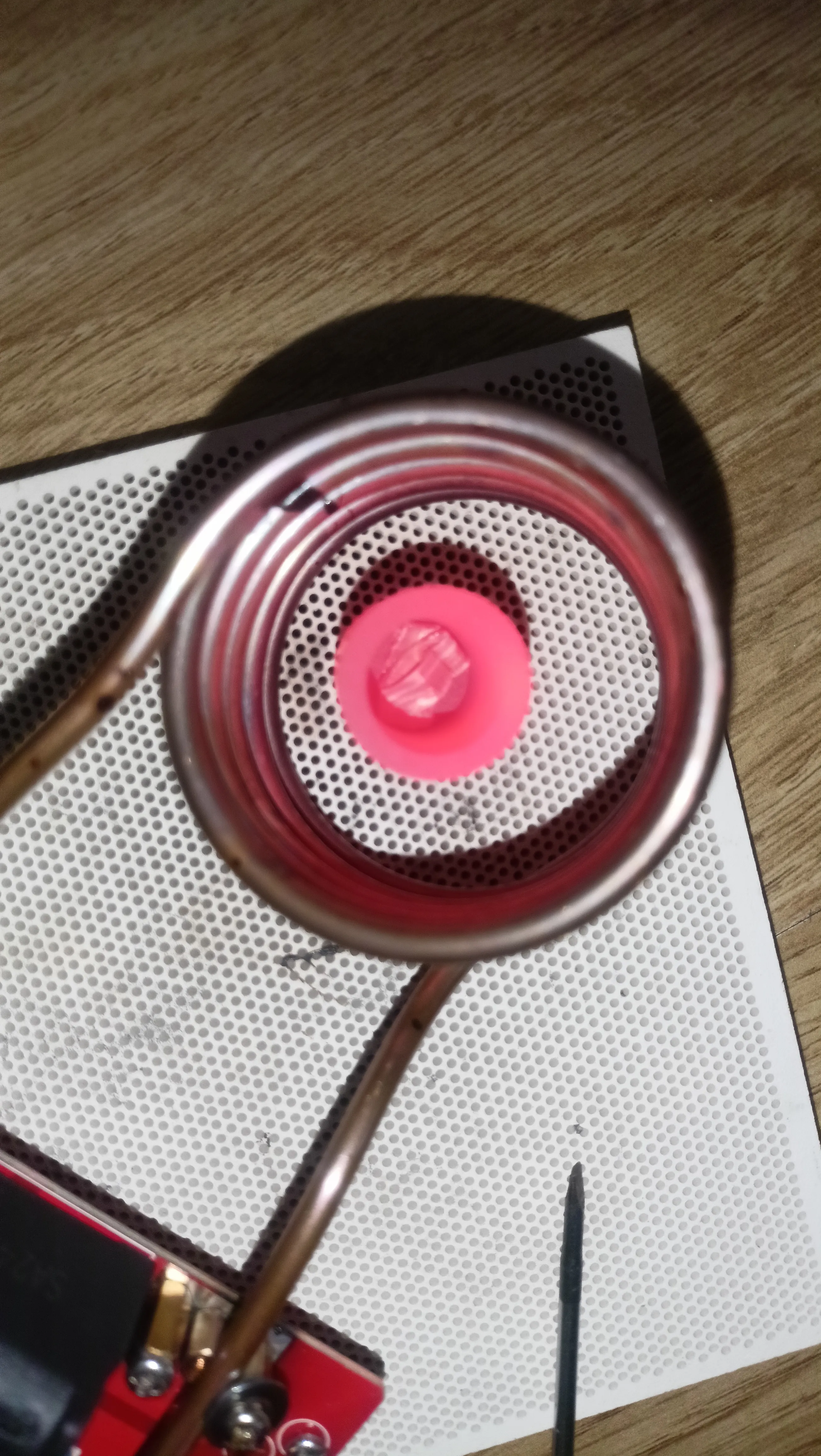
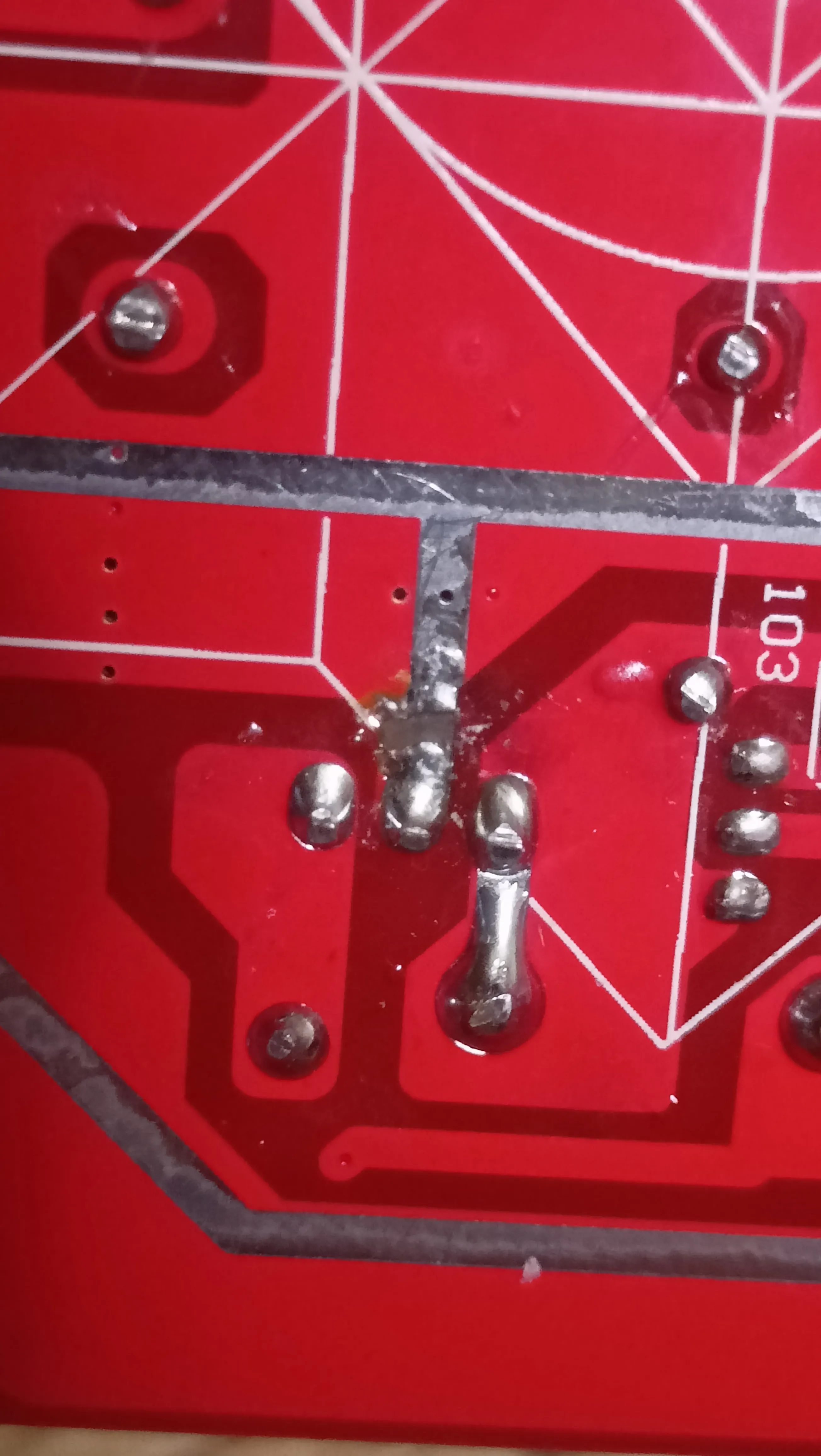
The test also revealed another problem, namely the utterly horrible “connection system” the board uses. Instead of a screw fitting or a hose clamp style connection, it is “implemented” with 3 standoffs and 4 washers. There is nothing redeemable about it. During one of the experiments, the work coil was jostled slightly, leading to the coil slipping, causing the formation of a hotspot in a thermal runaway scenario where surface oxidation from heating increased the resistance, leading to an even larger, self-fueling increase in heating. Now some of the copper is delaminated from the board and everything looks really gross and also like total shit. A decision was made to machine a better connector out of copper.
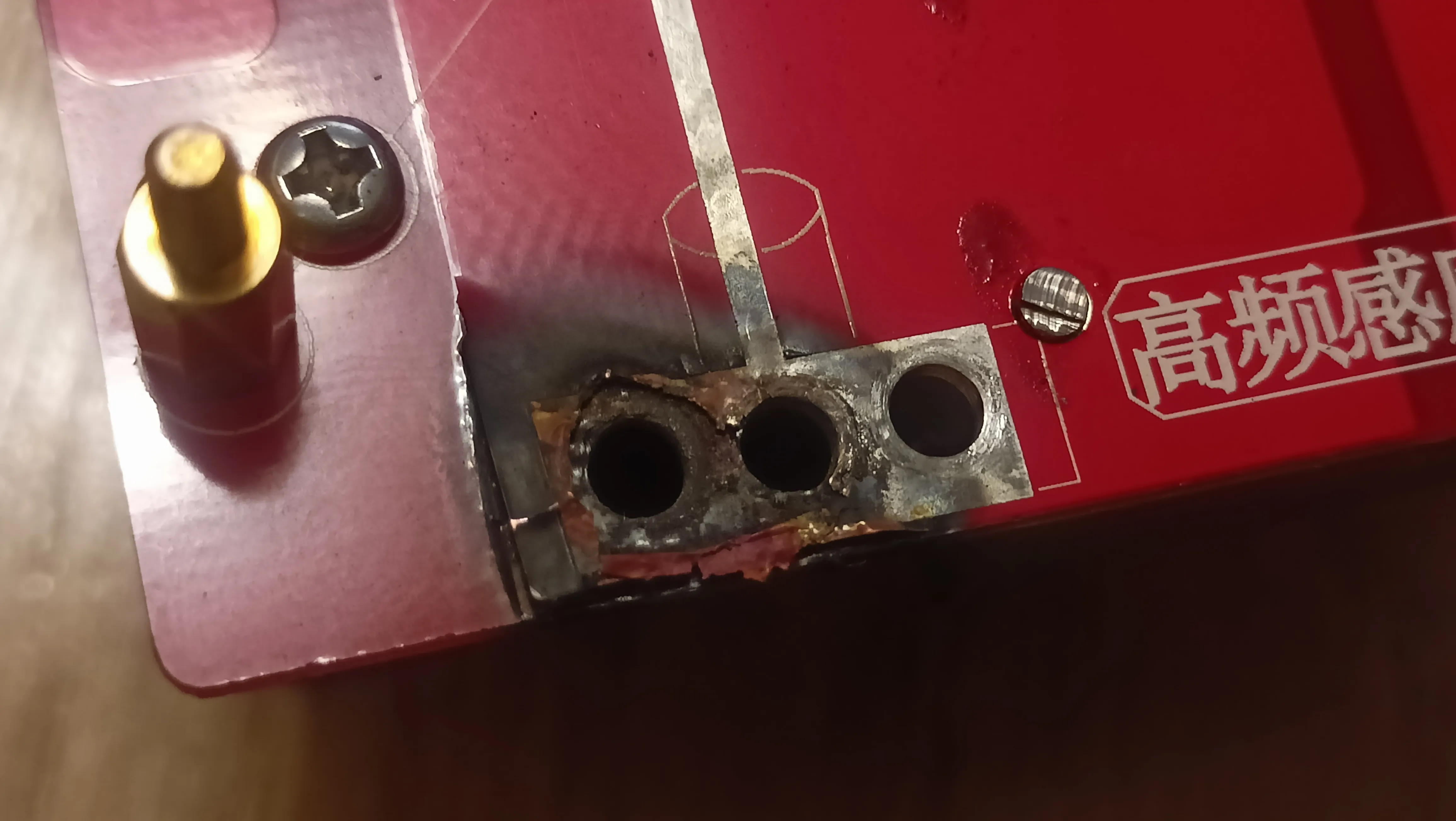
This is about where it ends for now. A new connector was designed but only half-finished. The power grid in the country collapsed yet again and I also ran out of sheet copper. Hopefully, the next installment of this series will not take a whole year to write.
Conclusions:
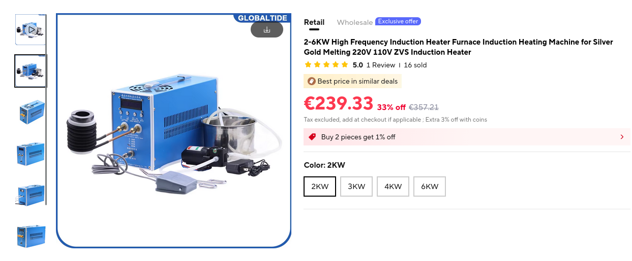
Is this worth it? On this early stage, I’m not sure, but I am more or less optimistic. If you have the money and are impatient it’s better to buy a premade all-in-one induction furnace like this (~300-400 euro). I decided against it because I do not have the money nor the space for such a big device, and I was aiming more towards a portable benchtop induction heater more than a workshop-sized part annealer.
As of now, there seems to be a lack of literature on using induction heating for chemistry (seriously, if you have any literature on this please add me on discord @arylation, I really could not find any designs for such a device thats not aimed for alloy making and maybe at best glass.). There is really much to be done, starting from figuring out a good crucible material for sintering reactive materials to temperature insulation and automation for such a device. Please await the next installments patiently. Peace.
Links
Aliexpress loves deleting listings. Here’s a list of descriptions and keywords for you to try to find similar components for when it all eventually linkrots
- Crucibles: https://www.aliexpress.com/item/1005004639272403.html “Slender 20x30mm graphite crucible”
- Honeycomb heat insulator plate: [already linkrotten] “Honeycomb Ceramic Plate for Casting Square Large”
- Induction Heater Board: https://www.aliexpress.com/item/1005003448464414.html “1000W ZVS Induction Heating Plate Kit”
- Power supply (1.2kW, 36V 33.3A): https://www.aliexpress.com/item/1005005191633442.html “1200W Switching Power Supply DC 12V 18V 24V 36V 48V 60V 70V 72V AC 100-240V SMPS CNC Adjustable Voltage For LED Stirp Motor”
Footnotes:
-
https://www.youtube.com/watch?v=Svual-PcOxE this was playing in the background while repairing the heater and it felt like im having a stroke for an hour ↩
-
https://spaco.org/Blacksmithing/ZVSInductionHeater/1000WattZVSInductionHeaterNotes.html re:coil size/coupling and also good resource in general ↩